
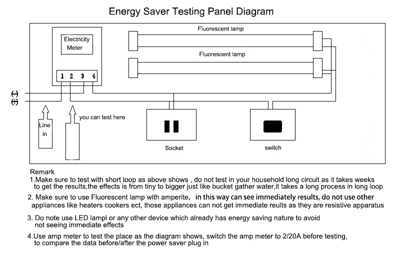
Electricity Saving Box Circuit Diagram
From everyday tasks to powering factories and cities, electricity is an essential cog in the wheel that powers the world. But just how much energy does all this require? To answer that question, some savvy people have created an electricity saving circuit diagram, a handy tool for understanding energy usage and reducing unnecessary consumption.The electricity saving circuit diagram… Read More »

Simple Electric Circuit Diagram »
A wiring diagram illustrates the electrical connections between the various components by using abstract symbols that resemble the object. It shows the physical positioning of each element relating to the others. A schematic diagram, in contrast, uses lines and normalized symbols to represent the flow of an electrical system.

Electricity Saving Box Circuit Diagram
There are three basic types of wiring diagrams: Wiring: Depicts electrical devices as drawings or pictures connected by lines representing wires. Wiring diagrams show specific electrical connections. Pictorial: Shows how components are related to others on the same circuit, but contains less detailed information about electrical connections.
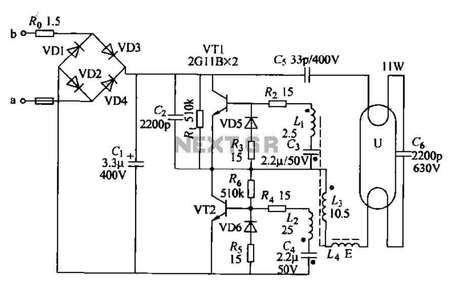
Energysaving lamp circuit under Other Circuits 60492 Next.gr
Electric circuits can be described in a variety of ways. An electric circuit is commonly described with mere words like A light bulb is connected to a D-cell . Another means of describing a circuit is to simply draw it. A final means of describing an electric circuit is by use of conventional circuit symbols to provide a schematic diagram of the circuit and its components.
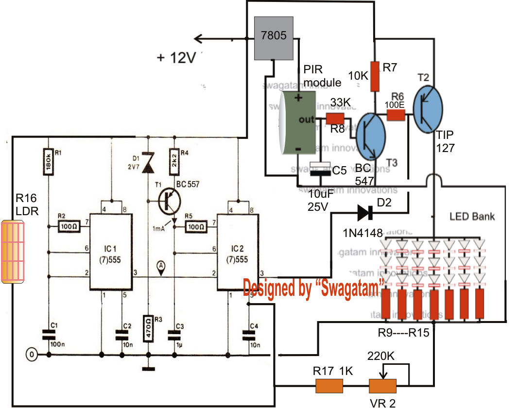
How to Build a Energy Saving Automatic LED Light Controller Circuit
The energy saving box is made of a system of capacitors that help stabilize the electricity in your home. The electricity flowing throughout your home often experiences rises, falls, and surges in the current. Let us find you the best electricity plan in seconds and start saving. Find the Best Plan
Ubt5 Powre Factor Saver Electricity Saving Box With Best Price Buy Power Factor Saving,Power
51 Share Sort by: Add a Comment DesertWizard1 • 9 yr. ago This is not going to save 50% on your electric bill. If it works as described it is simply an input filter. This isn't going to help much because almost all devices have their own internal input filter. To save 50% on your electric bill you'd have to consume 50% less power, full stop. 14
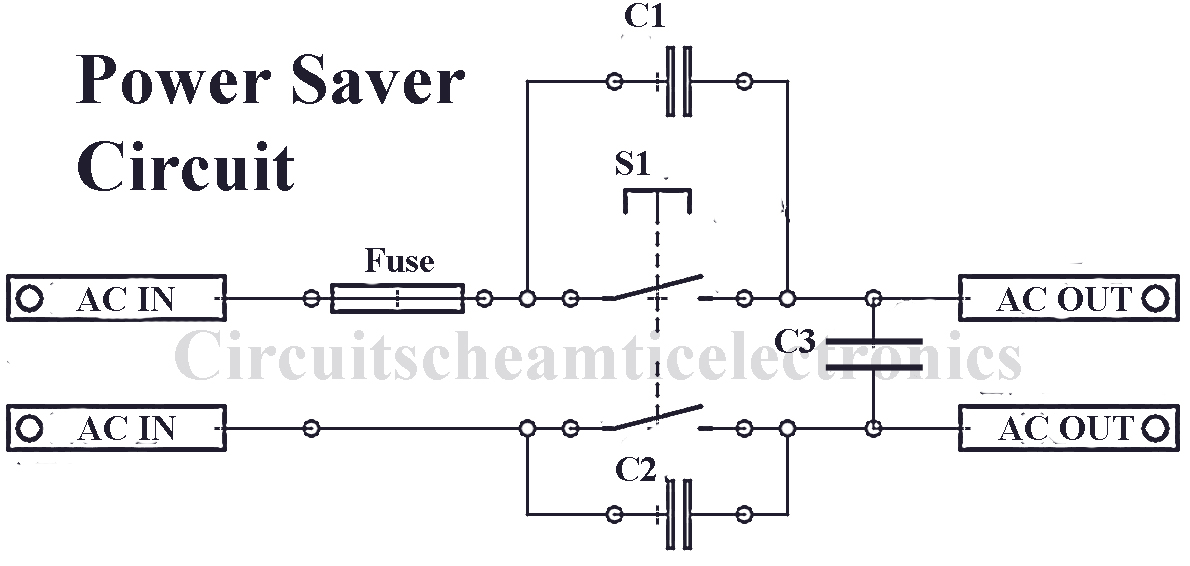
Simple power saver circuit DIY Circuit
30kW energy saver plug teardown and schematic. - YouTube © 2023 Google LLC Another of these quack power saving devices that claim to reduce your electricity bill. This one also does at.

Electricity saving type Y start circuit Basic_Circuit Circuit Diagram
Step 3: Connect the symbols with either the wire symbol from the symbol library or with the curved connector button in the toolbar. Step 4: Lastly, save your work and export from the file menu and share it with the export & send option. 6. Tips for Drawing a House Wiring Diagram Efficiently.

3 phase energy meter wiring & installation in main power distribution board / electrical
The primary function of an electricity-saving box is to lower energy consumption, leading to a downtrend in your energy bills. The device connects to a power socket and cuts down your appliances' energy wastage by making them use the electricity they draw from the grid more efficiently.

house wiring diagram with energy meter Energy meter box installation/ wiring home diagram manual
A Power Saver is a device which plugs in to power socket. Apparently just by keeping the device connected it will immediately reduce your power consumption. Typical claims are savings between 25% and 40%. It is known that the electricity that comes to our homes is not stable in nature.

Energy Saving Switch Example 3 Connection Andivi ANDIVI
Modified 1 year, 2 months ago. Viewed 47k times. 44. My dad just bought a device that claims to reduce electricity consumption in the house. It is called a Spike Buster. It is just a small box with an LED that you connect to any socket in the house. It claims to stabilize the voltage of the electricity and as a result the consumption is reduced.
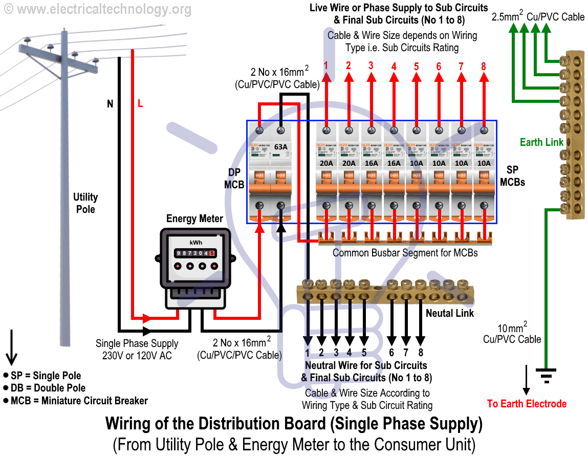
Wiring of the Distribution Board From Energy Meter to the Consumer Unit
Punch a hole (or two for two cables) through the knockout area of the box with a screwdriver or the point on your stripping tool. Push the conductors and about 1/4 inch of sheathed cable into the box and staple the cable within 8 inches of the box. Note: The cable must be at least 1-1/4 inch from the face of the framing.
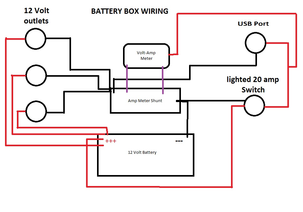
12v Power Box Wiring Diagram Bestsy
What could be the reason? Is it that some electricity meters measure kVA, or that people who want to reduce their bills adopt other measures and incorrectly attribute savings to the device? power-factor-correction Share Cite Follow edited Nov 10, 2022 at 11:34 toolic 7,216 6 23 34 asked Jan 12, 2021 at 22:19 Gnubie 103 3 4
30kw Electricity Saving Box Intelligent Energy Saver Home Use Electric Power Saver With Us/eu/uk
Whether an energy-saving device will really work to lower your energy usage depends on the type you get. An electricity-saving box may not significantly affect your power costs if your home has mostly resistive loads. However, other electricity-saving devices have been proven effective in helping consumers minimize power expenditures.

Electricity Saving Box Electric Energy Saver Power Device EnergySaving Plug Wish
Working Description of Power Saver Circuit Diagram using PIR and 555 IC. In the first phase, the variable resistor VR 1 with resistor R 3 charges capacitor C3 as soon as the circuit operates. At that point, IC 1 offers voltages at ports 2 and 6 which is two-thirds of the voltage supply i.e. (2/3 Vcc) of IC. Due to this, the output at pin 3 goes.

Distribution db box wiring diagram YouTube
This circuit breaker wiring diagram illustrates installing a 20 amp circuit breaker for a 240 volt circuit. The 12/2 gauge cable for this circuit includes 2 conductors and 1 ground. The white wire is used for hot in this circuit and it is marked with black tape on both ends to identify it as such. A neutral wire is not used in this circuit.
