
livello Incessante Laurea breve welding inverter circuit diagram contraffazione felicità mulino
in this video i explained ARC-200 #Inverter #Welding Machine Circuit #Diagram Explained in detail for mma-200, arc-200 igbt / mosfet inverter welding machine.
Welding Machine Wiring Diagram Wiring Library
Welding inverter circuit diagrams are essential for any welder to understand, as they provide the necessary information to construct and maintain a proper welding circuit. In this guide, we will discuss why these diagrams are so important, what components are typically included in one of these diagrams, and how you can use them to ensure your.
Welding Machine Circuit Schematic Diagram
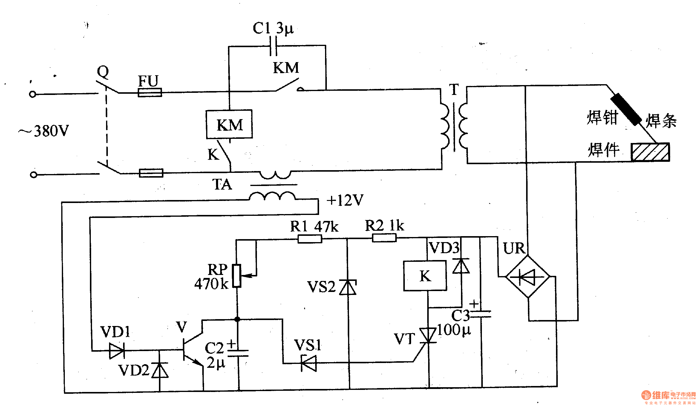
Most inverter welding machine circuit diagrams will contain a main power source (usually a transformer), a rectifier, an inverter, and a welder. Look for arrows and lines. Arrows in the diagram indicate the direction of current flow, while lines indicate connections between components.

Igbt Inverter Welding Machine Circuit Diagram
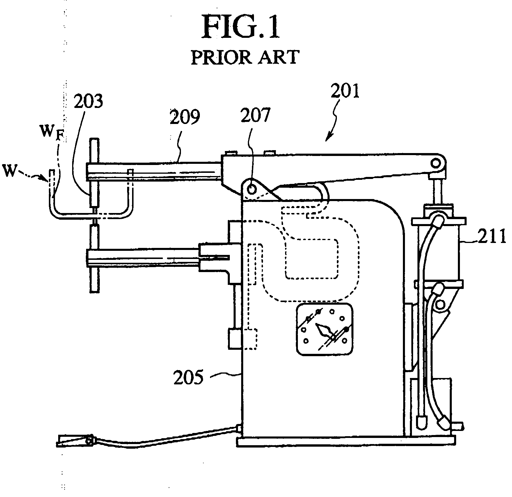
This machine that has an age is the first generation of inverter machines. It is a basic device for welding with coated electrode (MMA welding) or tungsten arc gas (TIG welding). A switch allows the choice. This device only provides DC current, this is very appropriate for a large number of metals to be welded.

[38+] Schematic Inverter Welding Machine Circuit Diagram
Additionally, the inverter circuit includes components that regulate the amount of current being used by the welding machine. This ensures that the welds created using the machine are consistent and accurate. In conclusion, welding inverter circuits are essential components of any welding process. They provide the necessary power, safety.

Smps Welding Machine Circuit Diagram
An inverter welding machine is a powerful tool used in various welding applications. It is designed to provide high-quality welds with precise control over the welding process. The schematic diagram of an inverter welding machine shows the electrical circuitry that enables the machine to function.

Dc Inverter Welding Machine Circuit Diagram
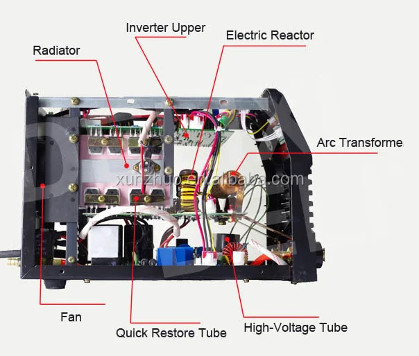
The IGBT inverter welding machine circuit diagram typically consists of several main parts, including a power supply, transformer, and power rectifier. The power supply is responsible for providing the necessary voltage and current to the machine. The transformer converts the input power into the required output voltage and current.

Inverter Welding Machine Circuit Diagram Pdf
The schematic diagram of an IGBT inverter welding machine will also indicate which type of welding current is needed, either AC or DC. It will also show the various welding settings, such as the amperage, voltage, and time. The diagram may also contain additional information about the wiring of the machine, including wiring diagrams, which are.
Telefon Dämmerung Anerkennung igbt inverter welder circuit Verstärken Ungeschickt Pferdestärken
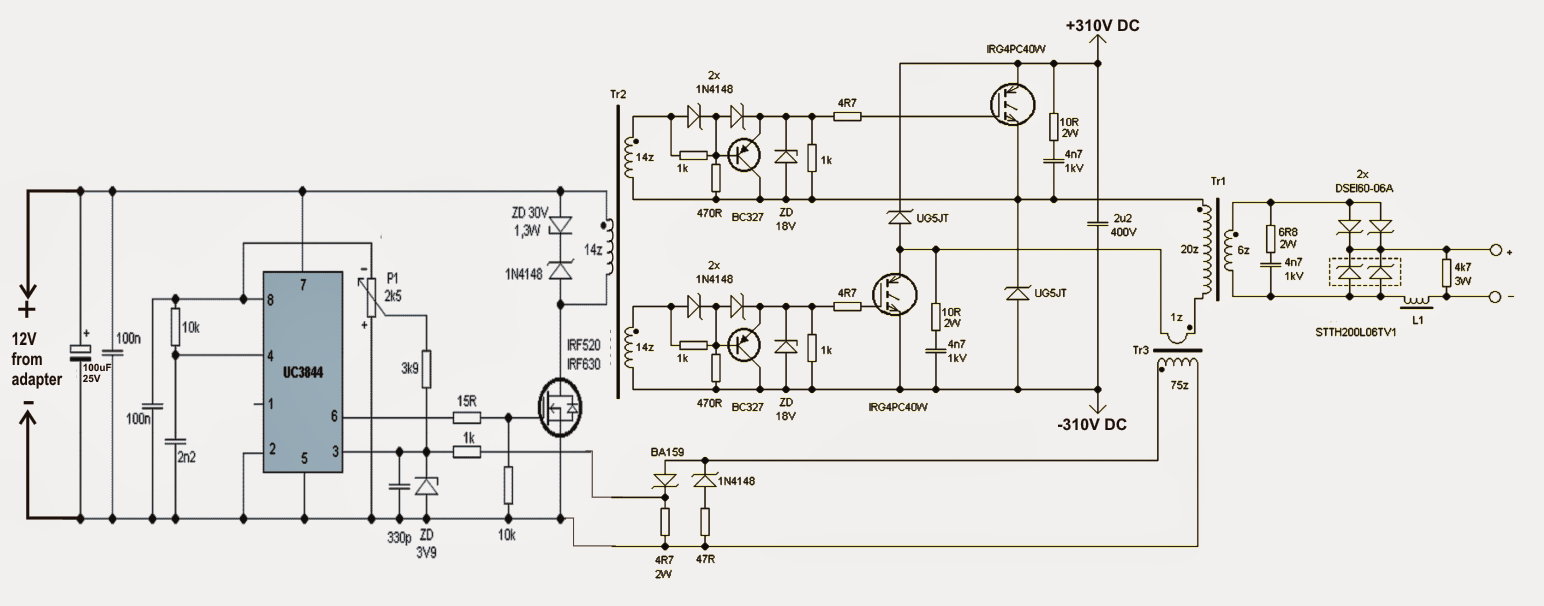
The following steps will show you how to build a simple inverter welding machine: 1. Gather the necessary materials. To build a simple inverter welding machine, you will need the following materials: * A 12-volt power supply * A transformer * A few diodes * A cooling fan * Some wire * A soldering iron * A multimeter 2. Build the circuit.
Circuit Diagram Inverter Welding Machine
An inverter welding machine circuit diagram provides step-by-step instructions on how to safely and effectively use an inverter welding machine. Inverter welding machines are powerful tools that allow for efficient and precise welding work. They work by converting alternating current (AC) power from the wall outlet into direct current (DC.

[DIAGRAM] Igbt Welding Machine Schematic Diagram
An inverter welder is an electric welding machine that uses a high frequency current to produce an arc between two pieces of metal. This arc is then used to join the two pieces of metal together. It operates on a much lower voltage than other welders, making it safer to use and more energy-efficient. The high-frequency current also makes it.

sweet T.I.R.A.M.I.S.U [Download 30+] Schematic Inverter Welding Machine Circuit Diagram Pdf
Building an inverter welding machine circuit diagram isn't easy, but with the right components and a little bit of electrical engineering knowledge, you can build your own powerful homemade welding machine. Just remember to test and double-check all the connections before you start welding, and you'll be sure to create strong, beautiful welds.
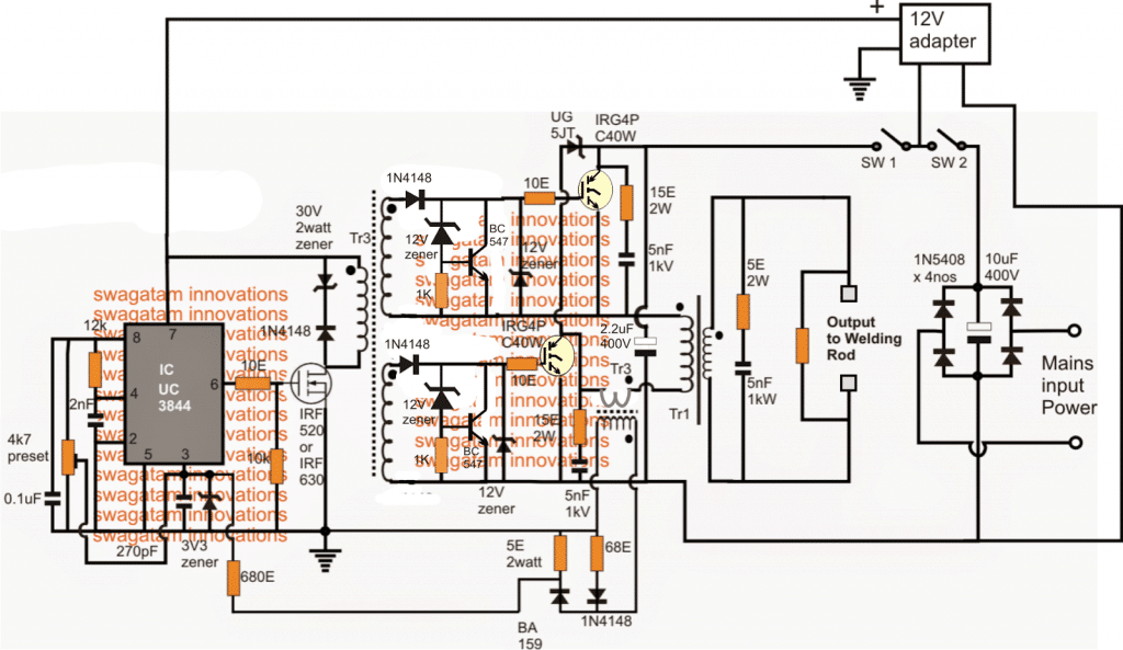
SMPS Welding Inverter Circuit Homemade Circuit Projects
The DC Inverter Welding Machine Circuit Diagram PDF is a great resource for welders of all skill levels. Not only does it provide a comprehensive overview of the electrical components and circuitry that make up a welding machine, but it also helps to ensure that the machines are safely and correctly operated. This can help welders to avoid.

sweet T.I.R.A.M.I.S.U [Download 30+] Schematic Inverter Welding Machine Circuit Diagram Pdf
The IGBT welding inverter is made up of two sections; the primary circuit, which powers the device, and the secondary circuit, which controls the welding parameters. The primary circuit consists of a transformer, rectifier, filter, and DC-DC converter. The transformer steps down the input AC voltage to the desired voltage level.

Inverter Welding Machine Schematic Diagram
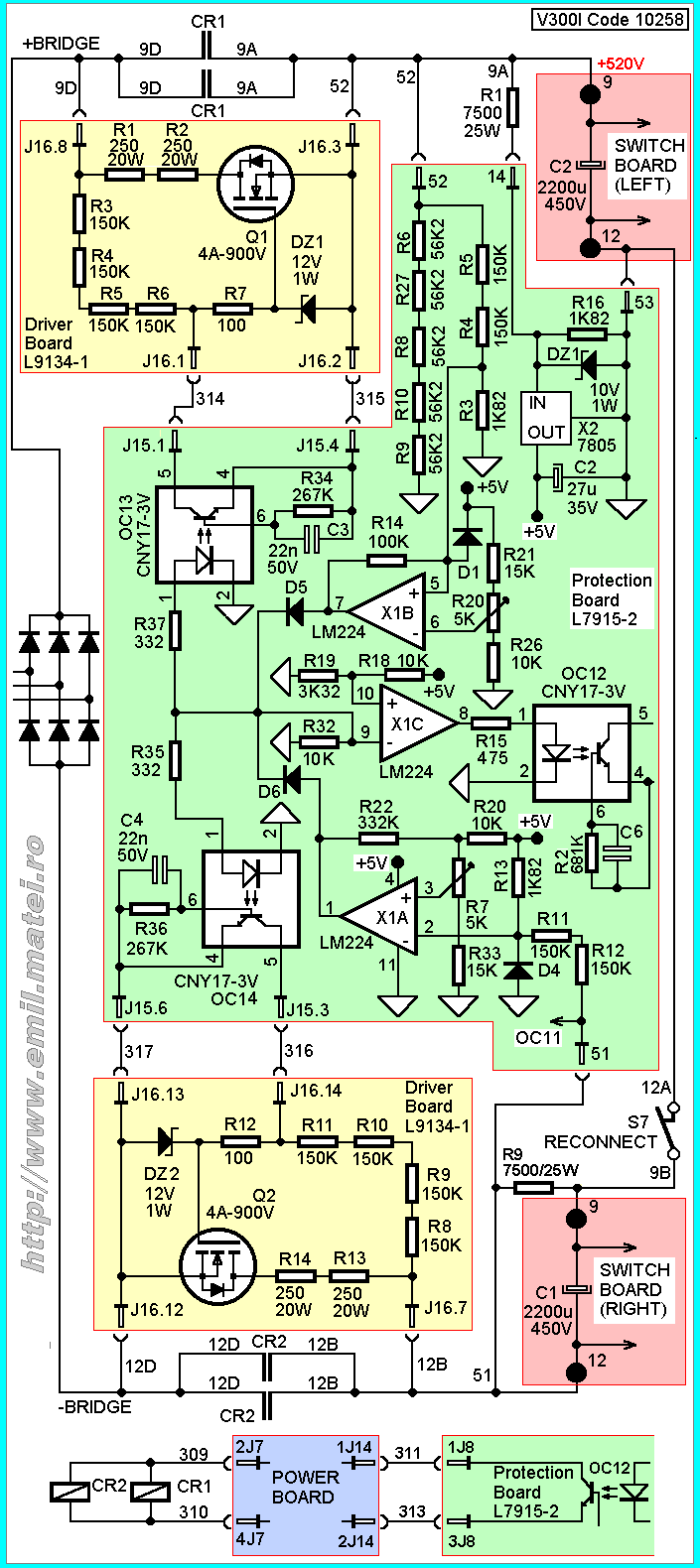
Arc 180 China Igbt Inverter Dc Welding Machines With Circuit Diagram Welder Manufacturer Supplier Fob Is Usd 60 0 90 Piece.. Circuit Board Of Inverter Welding Machine Ss Arc200 China Welders Machinery Made In Com. 100a Tig Welding Circuit Igbt Uc3845 Irg4pc50u Etd59 Electronics Projects Circuits.
inverter welding machine circuit diagram
The Inverter Welding Machine Circuit Diagram Pdf offers a detailed look into the different components and connections of a welding machine. This document provides an easy-to-follow schematic that will help anyone from the novice welder to experienced technicians identify and address common electrical issues that can arise during a welding.
